woodworking homemade shopmade craft
BUILDING BANDSAW
I decided to build a new bandsaw because I wished to show the building process steps one by one. The bandsaw is one of the motivations why I started up this site. I wish that many people in Japan experience the same as I have not found the woodworker who buit his own wood working machines by himself.
First I designed the machine on the drawing, and arranged the materials. Some of them are purchased. I have build already 3 units of the band saw including 2 failures (plus 3 desk type band saw units, also including 2 failures), therefore I could review the process. I anyway take photos, and movie. However I do not have movie software, I am looking for the good editor to uplord the process movie as soon as possible.
I found difficulties to build the unit while taping. But I will do the best because it is the purpose to record this process, and show on the site
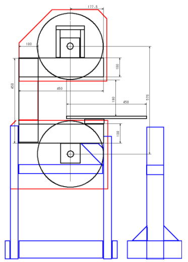
This is the basic structure. I have now the table saw and band saw. Therefore I made the frame by plywood of glued layers. In my case, 12mm thickness plywood x 5, total 60mm. Stand is made of 2x4.
Almost of overseas people make the flame of hard wood such al maple, oak etc. However in japan such material is much expensive. Usual 2x4 is not suitable as it is distorted. I made the frame of steel, and I believe steel structure is the best for making frame. But it would be hard for the people to handle. Therefore I think that plywood is the best answer.
I used the table saw at this time, but if you do not have it, you can make by circular saw or hand saw spending time.
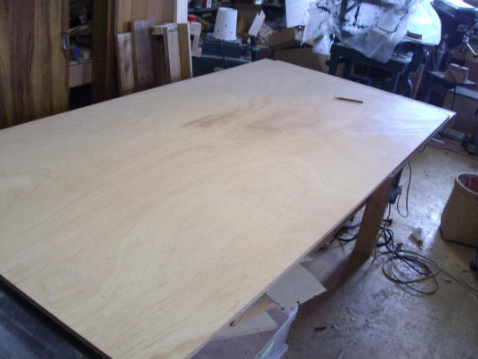
While waiting for the shaft and other items purchased on net, I started making the wheels. First, I cut out of plywood. My table saw, as well as shop itself, is not large enough to cut the plywood, I started by cutting by circular saw, nest jig saw, and finally by band saw.
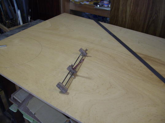
At first draw a circle by compass on the plywood and drilled at the center.
Cut the plywood by circular saw to the width of the wheel, next cut out rough shape by jig saw and finished by bandsaw.
When I build the band saw at the first time, I made the wheels by circular saw, jig saw and hand saw. It took time, but it is possible. Later wheels are finished precisely.
I used band saw when building 2nd and 3rd unit, but it was very hard as these unit were far from perfect.
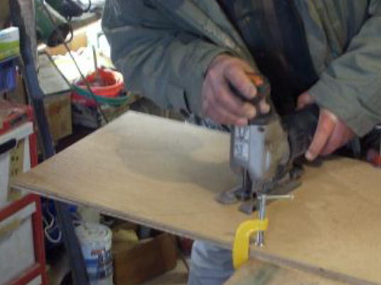
Rough cutting by jig saw.
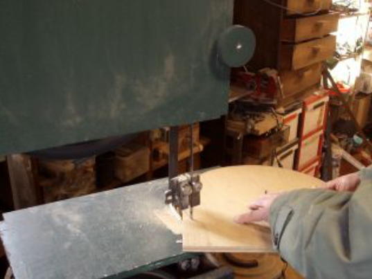
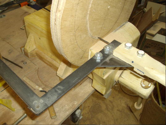
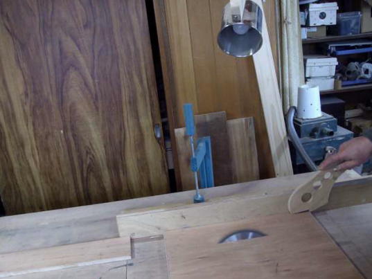
Finished by band saw. Set a temporally pin on the band saw table, and put the wheel center on it to cut correct circle.
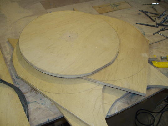
Other 4 disks are made by same method. First disk can be used as template. At this stage, the disk are made as accurate as possible. Later I will finish by lathing them to perfect accuracy.
Some people proceed this process by table saw. But I do not want as it seems dangerous.
4 plywood are laminated to make a wheel. At this time, 12mm thickness x 4 to 48mm thickness wheel.
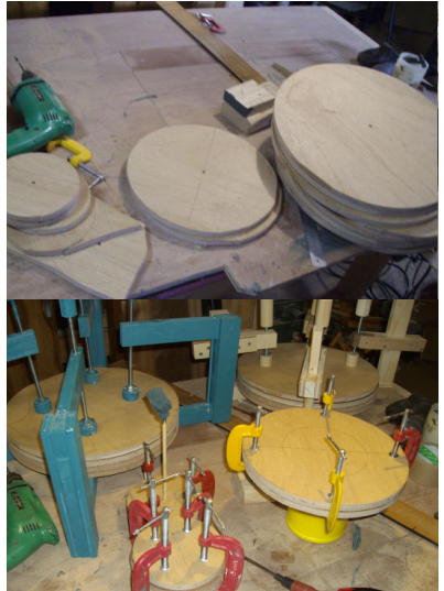
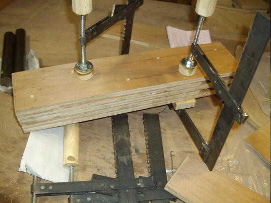
Cutting out the pulleys, bearing retainers, glued and clumped. I leave them overnight.
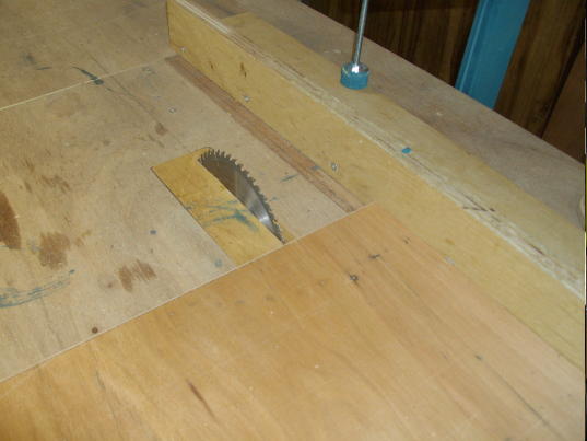
Cutting out flame parts by table saw.
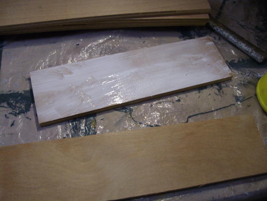
Glued the boards,
laminated and clumped,
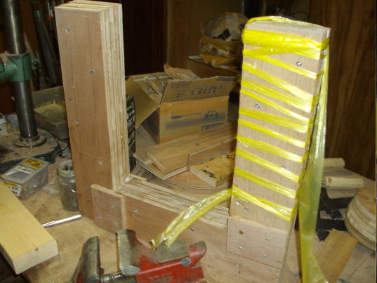
and forming "C" shape the frame. Already fixed by screws, therefore no need to clump.
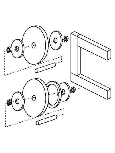
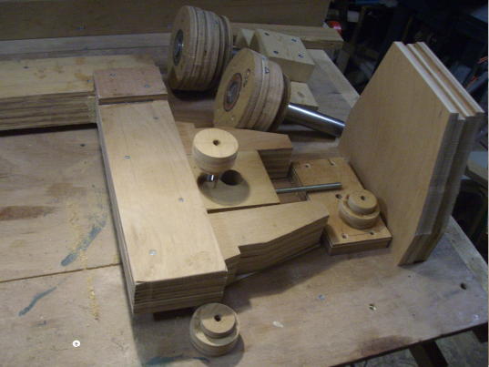
Configuration of the frame and wheels. Lower wheel is fixed and upper one is moveable to adjust
The shaft holder is also assembled by glueing.
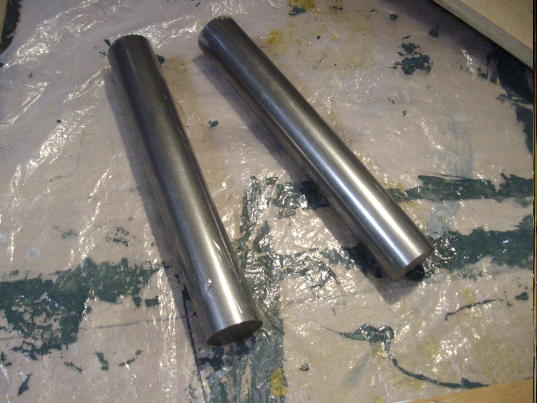
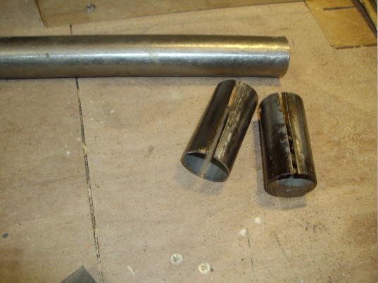
Shafts are delivered. Solid steel rod which minutely lathed so that they will fit to the bearings precisely. I do not recommend thin thickness pipe etc.
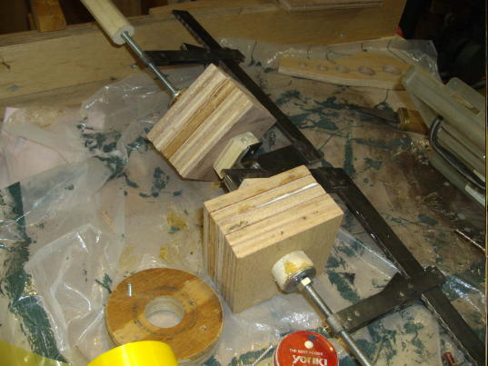
Cut the one of the bearing retainer out of the pulley material. I used the hand frame saw as the scroll saw is not powerful for this cutting. This shop made frame saw is quite useful. I can use cut piece of the band saw blade.
Once I made wooded frame saw, but I was not satisfied because balance of this wooden frame saw was poor. Steel frame saw is very useable for good balancing and enough blade tension is available.
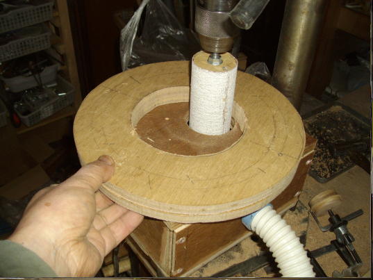
This is shopmade drum sander to use with the drillpress. Vacuum hose is attached to the dust collector. I made large, middle and small size drums. It works well however it is troublesome to install on the drillpress. Therefore I use it seldom. Usually hand sanding block is better to use for simple work.
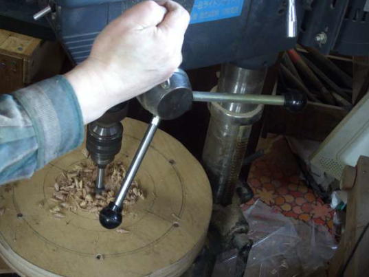
Make a hole where the shaft comes. It should be enough thicker than the shaft. I made 35É” hole for 30 É” shaft. If your drill press is enough large to reach to the center of wheel, you can make this hole by hand held drill. Or using the chisel, you can make this hole. Perfect correct
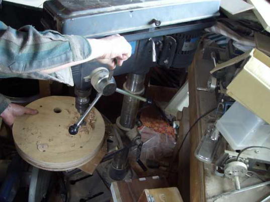
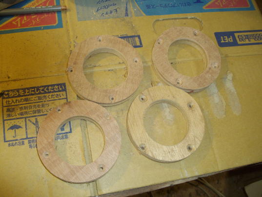
4 holes are made which is necessary to clump the bearing retainers later.
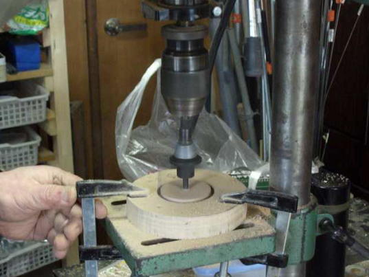
Make the holes on the bearing retainers. This hole must be made as the bearings are set very tightly. If it is loose, wheel will be failed. I used adjustable boring bit. You should test boring before the retainers to confirm the hole size is adequate.
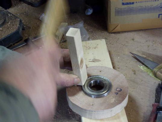
Setting the bearings. Use some wood blocks to push the outer ring by hammer gently. Never tap on the inner ring. Bearings must be inserted to be flat on the retainers' surface.
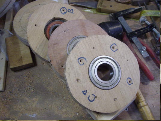
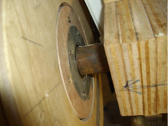
Bearing retainers with the bearings set in. Outer rim is not finished. The screw holes are drilled where the retainer is fixed on the wheel.
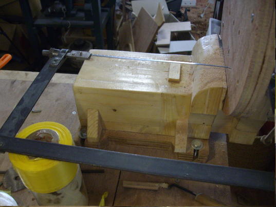
Set the shaft thorough the bearing of the retainer and fix the temporary pulley so that I can turn the retainer.
This is the blade guide. At this time I made it as the blade runs between 2 wood blocks on a bearing.
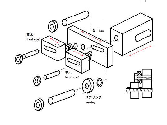
Construction sketch
Shaft holders and a housing are made by table saw.
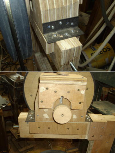
Upper shaft holder and the housing
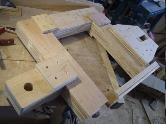
Completed upper shaft holder, and the housing, also lower shaft holder are assembled with the frame as trial
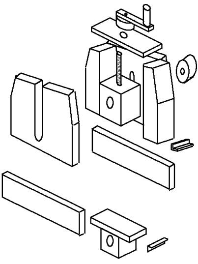
Configuration of upper and lower shaft holders and the frame.
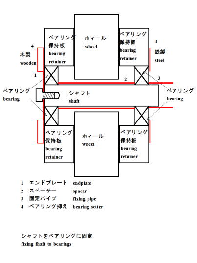
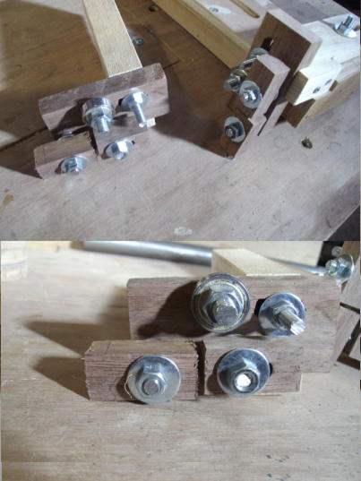
It is necessary to fix the bearing to the retainer so that it doesn't come out while running, or misaligned. If it does, the blade would cut or jammed resulting sometimes serious damage. To fix the bearing to the retainer and shaft, the bearing setters are mounted as shown.
I made the end plates of 2mm thickness steel plate by the holesaw. But by scroll saw, of cause or hack saw and files. Not severe accuracy is needed. To fix the bearings to the shaft, I put a peace of pipe same as inside of the bearings.
And the fix rings which push the bearing into the position are shown. I made of plywood on outside, and of 1mm thickness steel plate on backside.
I do not want to glue the bearing in the retainer as it would be necessary to position the bearing in some trials.
Spacer which covers the shaft to keep the bearing aligned. I made this spacer of the thin thickness pipe found in my junk box.
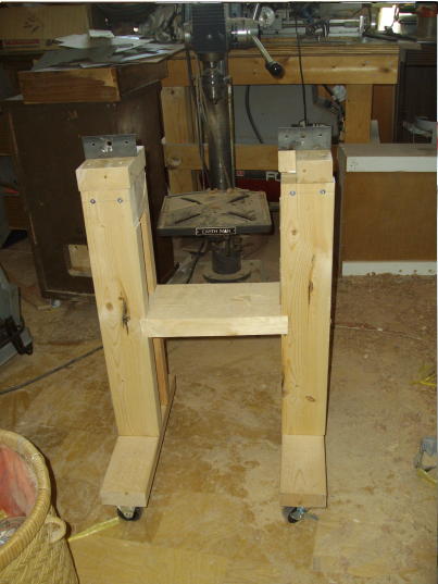
Stand is made of 2x4. The size is a little smaller at this time to save space in my small workshop.
I tried to assemble the frame, a wheel on the stand. It seems smaller than imaged. Table is much smaller than planned one because I also wished to save space in the workshop. Usually this sized table is enough, and if necessary I will place larger table on it.
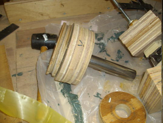
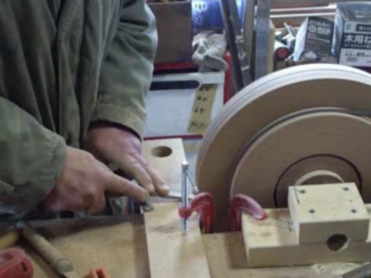
First, I turned to shape the bearing retainer. I set the bearings of the retainer on the shaft which is fixed on the workbench. The retainer can be driven by the motor so that I can turn the retainers. I turned the retainers by chisel as shown.
This process is same for the pulley and wheels.
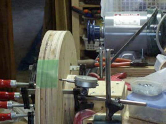
Before turning the wheels, their surfaces should be completely aligned. I set the wheel between 2 bearing retainers, and set on the shaft through the bearings. Retainers are clumped on the wheel through the holes of the wheel at 4 positions temporarily. Then I turned the wheel by hand and check the surface alignment by the dial meter as shown. Tap the wheel so that the movement of dial meter indicates to minimum. Tighten the clumps at when dial meter indicates the minimum, and screw the retainers to the wheel. Wheel surface alignment is now completed.
I fixed the pulley to the aligned wheel to turn the edge side by the chisel to make perfect circle. When turning the edge, make the curved surface, i.e. both side of the center line slanted down to the edges. This is important to keep the blade in position. Of cause the slanted sides must be symmetry.
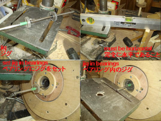
Now I prepared the jig to take weight balance of the wheel. I used the jig which I used previously. I made 2 polycarbonate discs to inset in the bearings with a 6mm diameter shaft at the center. Plywood discs will be OK. Size must be accurate.
Stand on which the jig shaft is placed should be perfectly horizontal and rigid as shown.
Setting the jig in the bearings.
Taking wheel balance is very important to avoid later problems, therefore I took enough time. Putting the whole assembly on the horizontally stand so that the wheel can turn freely. I turned the wheel by hand and waited it stopped. I repeated this several times to find the heaviest point of the wheel where I made the balancing holes.
I repeated this work until the wheel stops at any position.
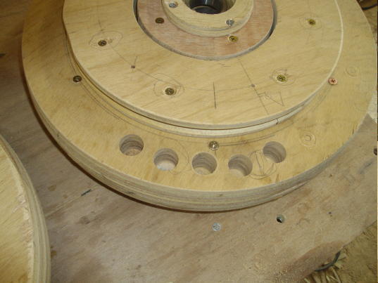
This is the photo of the wheels on which the balance holes are made.
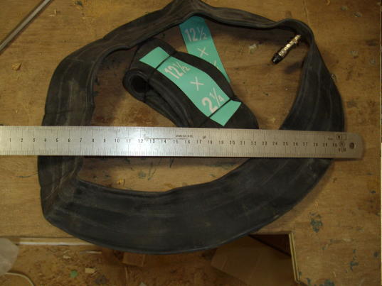
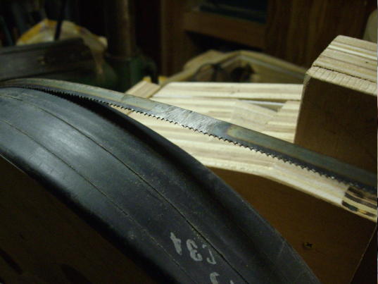
Rubber rim is glued on the wheel. I used the bicycle tube 12".
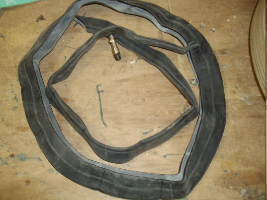
I cut the tube as shown.
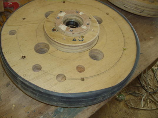
I glued the cut tube on the wheel. The wheels are completed.
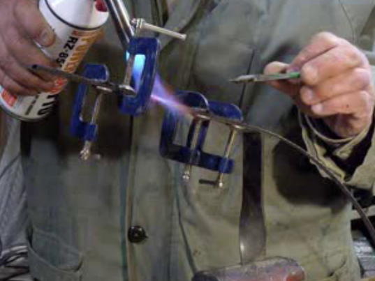
I tried assemble the wheels on the frame which fixed on the workbench. Then I set the blade on the wheels in suitable tension. I made this blade by blazing the cut blade from the long coil. Blazing blade is easy, so you can do it satisfactorily after several trials.
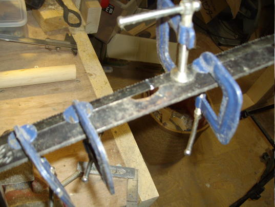
Cut ground and slanted edges of the blade are blazed, and filed smoothly.
This way is enough proper. Welding method is also useable but I prefer blazing method as it is easier.
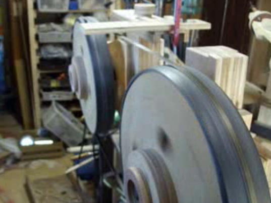
I tried to drive the wheel to run the blade. I could cut the piece of the wood very well. Later I will align the wheels much better.
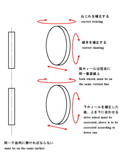
Logically to say, Alignment of the both wheels would be automatically perfect. However, it is not acceptable in fact. Therefore, I fixed the lower wheel to the frame in proper alignment, and adjusted the position of upper shaft holder housing as shown. It must be done enough accurately to avoid cutting or coming off of the blade.
Once wheel alignment is done, it must be fixed. However it would be misaligned after long time because of deformation of the frame. Therefore it is necessary to make it adjustable later, I think.
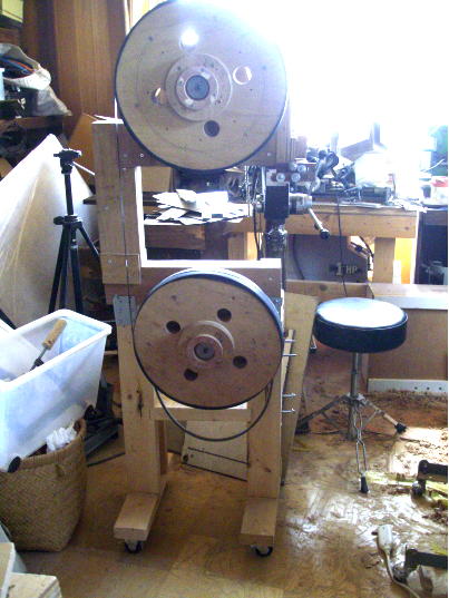
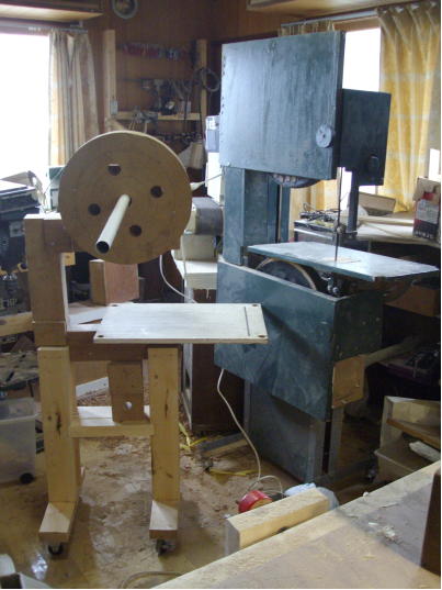
I once tried to set the frame unit on the stand. I found this stand is too low for standing work. If necessary I will remake the stand.
Final alignment is by moving the upper housing. I tapped it by rubber hammer while turning the wheels to see if the blade runs accurately.
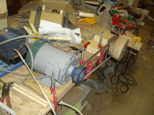
I purchased an induction motor, 200v 3ph 400W. As the power supply is 100V AC single phase in my shop, I need an inverter to run the motor in my shop. Also I needed smooth speed control. 400W is enough for my use, but the larger motor would be OK if you need. First, I planned to use a motor drill, however speed control is not so easy. Another problem of such drill is continuous use is up to 30minutes or so. And big powered drill is too expensive. Therefore the induction motor is the good choice, I think. The inverter is useable for other motors, therefore it is much advantageous in total.
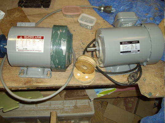
Now the purchased motor is delivered. Therefore I made a motor pulley of plywood. However this pulley is quickly broken. Probably the strong impact when motor starts causes this damage. The I additionally purchased on net a motor pulley. It takes 15days as this is May holiday season. I ran the bandsaw with the motor and pulley which are used in the present unit.
The motor is installed.
The unit runs and works properly. Of cause it can cat the wood pieces good. I will see for a while and adjust if necessary.
I applied black and dark green paint to prevent moisture.
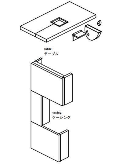
Table and casing are shown. The table is rather small but I think this size is good enough for usual use. If necessary I will put the larger table on it. This table can tilt up to 45degree. Tilting and locking mechanism are simple. If very heavy work is usually on the table, it must be more rigit
The casing is necessary to prevent any accident such as the cut blade hit you. This casing is locked by the simple snap lock.
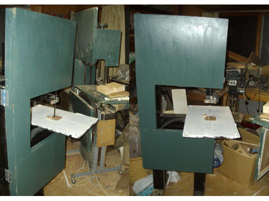
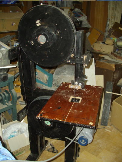
The band saw is completed. The present bandsaw is shown behind. These 2 bandsaw unit take space too much in my shop, but I will use 2 units for a while. I set the fine blade on the new unit to cut the hard wood or metal material.
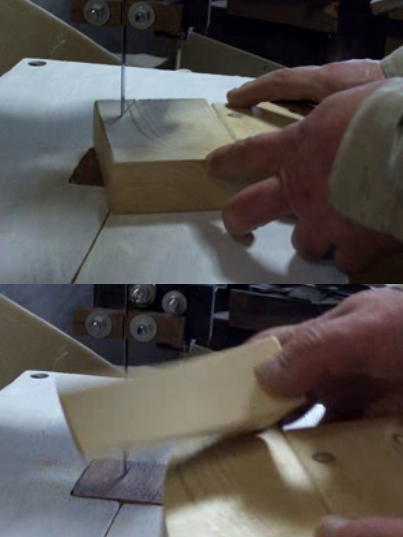
The cutting sample is usual 2x4. Cut surface is quite smooth, but it takes time. It can cut the metal such as aluminum, brass and thin soft steel.
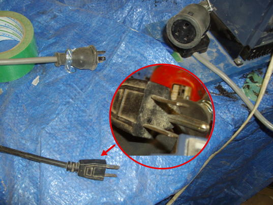
The proper connectors for the motor and inverter are not available in ths local town. I temporally used single phase connecter with the earth connecter to use 2 bandsaw unit. I will change them with the regular ones later.
I noted some points
1)Å@Cost
I used the material at hand as much as possible. However if I bur all of them, the total cost is estimated, in my case, around 60 thousand yen. It will varies according to various conditions. Any way it woud be less expensive than purchasing new unit.
2)Å@Material
I used the wood for main parts. In japan the hard wood such as oak, maple or ash is very expensive, therefore usual plywood is good, I think. For the previous unit, I used steel frame which I believe it costs lowest amount and enough stable and rigid. But if you do not suitable experience nor tools, it would be hard to use such steel material. Therefore I used plywood and 2x4 at this time.
For the wheels, the plywood or MDF is used. On the other hand, many people overseas use variould tires of bicycles etc. These tires are available in Japan. I have not tried to use the tires, but it would be possible.
As to the motor, overseas people use the used ones took out from the jank machines such as pumps etc. Out put is between 1/2Hp and 2Hp. In my case, 1/2Hp, i.e. 400W. I needed smooth speed control, therefore the induction motor and the inverter are the best choice, I believe.
3)Å@Tools and machines
If you have the bandsaw, tablesaw, floor drill press, it is ideal. But, of cause you can build without such machines .However at least, bench drill press, motor drill, circular saw are necessary. And usual hand tools such as saw, hammer etc.
4)Å@Blade
First I bought the ready made blade tor usual bandsaw on the market. But these blade are too expensive and I could not afford to buy so frequently as blade was frequently cut on my shopmade bandsaw. Later, I bought the blade coil which is 30meters in length, and cut in suitable size to blaze the end to make matching blade. Blazing technology is easy to learn after several In my case, the coil blade costs around 10 thousand yen on net.
5)Å@Building period
In my case, it took around 1 month from desigining to complete. It varies according to skill, devise, tools and machines. I estimate it would 10 days at maximum if you prepare well and concentrate on work.
To the next
Article Index
return to home